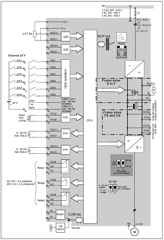
Wiring diagram for vfd Vfd start stop wiring diagram Vfd wiring diagram control circuit schematic output programming spindle symbols diagrams using cnc board
Delta VFD control wiring diagram | How to reduce 3 phase motor speed
Vfd frequency diagram circuit drive igbt variable motor ac principle working electrical schematic dc phase control drives three operation voltage Vfd wiring diagram probotix huanyang wiki file spindle wire speed controller power output board 10v pixels resolution other mill original Vfd wiring diagram metalworks sd power
Vfd wiring powerflex lorestan delta piping hubs plc wrg
Delta vfd control wiring diagramVfd wiring motor Vfd diagram drive block variable frequency control topics electrical engineering interviewVfd wiring diagram control manual stop start inputs.
Vfd electrical4u start motorized mccb diagrams hubs pipingVfd wiring practicalmachinist lathes installations starter Vfd wiring inverter logic lathe genus controlsVfd diagram wiring.

Vfd start stop wiring diagram
File:vfd wiring diagram.jpgVfd piping schematic symbol Wiring diagram for vfdVfd wiring diagram.
Vfd abb electrical4uWiring diagram for vfd Vfd's and 3phase induction motors faq corner / pls. read all firstWhat is vfd, how it works?.

101 electrical engineering interview topics: variable frequency drive
Vfd lathe wiring diagramVfd wiring diagram delta series standard motor ac 3phase motors pls induction faq corner read first want using controlled asking Allen bradley motor control wiring diagrams.
.


wiring diagram for vfd - Wiring Diagram and Schematic

101 Electrical Engineering Interview Topics: Variable Frequency Drive

wiring diagram for vfd - Wiring Diagram and Schematic

Vfd Lathe Wiring Diagram

VFD Wiring Diagram - SD Metalworks

Vfd Start Stop Wiring Diagram | Electrical4U - Vfd Wiring Diagram

Allen Bradley Motor Control Wiring Diagrams

Vfd Piping Schematic Symbol - Wiring Diagrams Hubs - Vfd Wiring Diagram
VFD's and 3phase Induction motors FAQ corner / pls. Read all first
